


As of 15th of Feb 2018, I had never worked on the innards of a gearbox. I know how everything works, but have never needed to touch them or assemble them, so I knew this was going to be a steep learning curve.
I had contacted a few gearbox places, but I was either flat out ignored or no one was interested to work on a gearbox that was already pulled apart, for reasons I later found out to be totally acceptable. So I took it upon myself to learn everything from scratch as it might come in handy in the future (hopefully I won't have to do this again).
So out came all the innards which were sitting patiently in a wooden box:


My first plan of attack was the countershaft as the previous owner had already removed the bearings on this and the 4th and 5th gears which require a press (or as I've found out, can also come off with a couple of love taps).
Out came the countershaft and gears/synchros/bearings laid out on the table:

At first glance I was thinking "wtf am I getting myself into" but figured if I can put it together and pull it apart multiple times, I can eventually get used to it and be comfortable with it.
Upon handling the countershaft, it became a problem having to hold it up when measuring synchros/gears. Laying it on its side would cause everything to move around so I made a shaft-holder-thingy out of scrap timber from a wooden pallet I got from the side of a factory
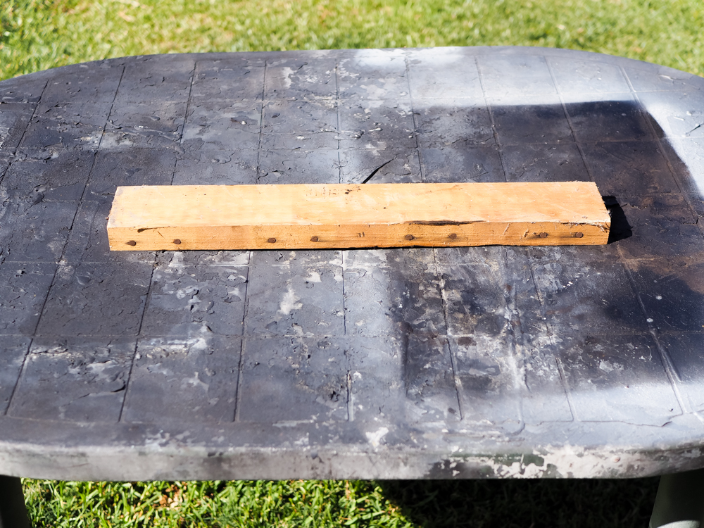
Measuring the shaft to make sure it slots in nicely

Measuring 1st gear to make sure it doesn't overhang over the base of the stand

Onto the saw

A couple of brackets later the base is created


Measuring 2 parts of the shaft so the top piece is adjustable when I eventually use the stand for the mainshaft

Same sized hole cut in bottom and top piece


Then it was time to adjust the upper piece to make sure the teeth on the shaft slot in without passing it so the 1st gear collar sits flush


Better


Now we're ready to start measuring clearances
The stand was done and working as intended


I think most people at this stage would just buy brand new synchros/dampeners/springs/cones, but in the spirit of this build, I wanted to see how all of the OEM parts measured up. This way I can learn what each part does instead of just replacing it with brand new parts and putting it back together which wouldn't give me the same opportunity to learn how this black magic works.
First step was a visual inspection of synchros/teeth


Pointed tips as opposed to blunt tips is what we were after.
Next was figuring out which way the friction dampeners sat in their corresponding gears whilst pointing the correct direction to sit in the synchro hub for 1st and 2nd gear
There are notches on the 1/2 synchro hub which corresponds to the tabs on the dampeners
1st gear side


2nd gear side


They can go in opposite ways and cause issues (everything seems to assemble fine even when the dampeners are back to front).
After getting that out of the way, it was time to measure everything else


Everything cleared within spec

The only parts I will be replacing on the countershaft will be spring washer/ballbearing and the needle bearing above the 5th gear.
Whilst the gearbox is apart I will also be replacing the 5th gear for the main and counter shaft to that from a DC4 GSi gearbox so I can achieve 100km/h speeds at <3000rpm seeing as that gear will only get used on the highway, I might aswell make it at the lowest RPM possible.
That's it for the countershaft until my bearings arrive which will just drop on.
Next up: Mainshaft